On this website we collected teaching modules for basics in microscopy which were developed by GerBi-GMB members. Feel free to use the teaching modules as input for your own teaching, and let us know, if there are questions.
The basic teaching unit is called a module, covering a defined set of topics, e.g. ‘basic microscope optics’ or ‘fluorescence’. While modules generally cover topics exclusively, some overlap may occur, such as PMTs covered in ‘confocal’ and ‘multi-photon’ modules. Several modules can be combined to a course to include all topics which are required to master a specific microscopic technique. For example, a course for confocal microscopy will include a module on confocality but also modules on fluorescence, basic microscopy, etc.
The recommended student:teacher ratio is given as S/T: [optimal]([maximum])
For the practical parts there is also a student:instrument ratio given as S/I: [optimal]([maximum]); instruments can be microscopes, analysis workstations, laboratory benches, etc.
Modules required to start this module: none
1. Theory (S/T: 12 (20)):
- Refraction at the lens surface and chromatic aberration.
- The compound microscope: beam path and properties of objectives, oculars and condensers
- The stereo microscope: beam paths for oculars and camera
- Finite and infinite optics
- Spherical aberration and coverslip thickness
- Diffraction (Airy disks)
- Resolution (Rayleigh, Sparrow, Abbe, FWHM)
- Aperture angle, NA and influence on resolution
- Immersion
- Köhler alignment
- How to keep microscope clean
2. Practice (S/T: 2 (4)) (S/I: 2 (4)):
- Building a ‘compound microscope’ with simple magnifying lenses
- Setting up Köhler alignment
- Working with immersion
3. Material
General Resources
Presentation
The SD 1 Basic Microscope Optics (BMO).pptx (author: Steffen Dietzel) contains a Powerpoint presentation with slides for a lecture on Basic Microscope Optics.
Web resources
- Basic Concepts in Optical Microscopy at the Optical Microscopy Primer at the Florida State University.
- Zeiss brochure “Microscopy from the very beginning” with over 50 pages gives nice introduction for the beginner. The same is available in German, “Mikroskopieren von Anfang an”. The link to the pdf changes every once in a while, your favorite search engine will help. You may have to create a free account on the Zeiss website to download.
- Video Understanding the Light Microscope by Peter Evennett on BioDIP you tube channel.
The tutorial is presented in one piece, so that it can be viewed in logical order, but its components may be viewed separately by reference to the time-points quoted.
-
- Conjugate Planes in the microscope (0 – 21:00 min)
The optical system of a microscope embodies two series of planes which are conjugate – optically linked, as images one of another. These are the ‘Field’ set of planes consisting of the object and its images, and the ‘Aperture’ set of planes which includes the light source (lamp filament) and it subsequent images. These planes are demonstrated here using a specially assembled microscope and video camera system. - Diffraction and the microscope image (21:00 – 50:51 min)
The most important function of a microscope is resolution – the ability to handle information about fine detail – and this is limited by the phenomenon of diffraction. Two factors are involved – the wavelength of the light, and the Numerical Aperture of the objective lens. The importance of these two factors was demonstrated in 1873 by Ernst Abbe in his ‘Theory of the Microscope’, and illustrated by a series of experiments. These experiments are demonstrated here, again using the specially-adapted microscope. Understanding this section will benefit from having followed section 1. - Dark-field Microscopy (51:41 – 59:40 min)
The second important function of a microscope is to provide contrast in the images of transparent and otherwise invisible objects. Dark-field (or Dark-ground) microscopy offers a simple and inexpensive method of enhancing contrast. It is explained here as a sequel to the Diffraction Experiments, using the same demonstration equipment, and should therefore be viewed following sections 1 & 2. - Phase-contrast Microscopy (59:40 min)
This section demonstrates the principle of a second system of enhancing visibility of transparent objects, Phase Contrast. Again this is demonstrated using the equipment as in earlier sections, and it should therefore be viewed following these.The video was enabled by German Research Foundation (DFG) core facility funding of the Biopolis Dresden Imaging Platform (BioDIP) and has been recorded by Christian Spataro. link to teaching material about basic optical concepts on BioDIP website and has been recorded by Christian Spataro.
- Conjugate Planes in the microscope (0 – 21:00 min)
- link to teaching material about basic optical concepts on BioDIP website
- In German only: Grundlagen der Lichtmikroskopie an der Uni Wien.
Refraction and chromatic aberration
- Refraction and total internal reflection can be demonstrated nicely with laser pointers and a glass cube or a large plastic cuvette filled with water. Pond water is preferable since the scattering particles allow to follow the beam path from a side view easily.
- Refraction can also be demonstrated nicely by glueing a coin to the bottom of a cup. Stand such that you just cannot see the coin and slowly add water to the empty cup. Watch the coin appear magically. See linked video below
- Chromatic aberration can be demonstrated with red and green laser pointers and glass prisms. If you put the arrangement on a normal table, have the students standing, so that the laser beam is not on eye level, to minimize eye injury risk.
Webresource:
- Video Coin-in-cup on BioDIP you tube channel demonstrating refraction: for this video a coin was glued to the bottom of a cup to keep it in place
- Schemes and images illustrating chromatic aberration in the respective Wikipedia article
The compound microscope: beam path and properties of objectives, oculars and condensers
Building a ‘compound microscope’ with simple magnifying lenses
What you can show/ explain with this:
- Intermediate image
- Roughly calculating the numerical aperture from lens diameter of the “front lens” and the “working distance”
- Why do you need Köhler alignment? (with modification 1)
- Chromatic aberration (with modification 2)
What you need:
- 2 or more magnifying glasses, that can be loupes, microscope oculars, linen testers etc. A relatively strong lens will act as objective, a weaker one as eye piece.
- a light emitting object, that can be a low power halogen bulb, an LED or – if compliant with your safety regulations – a candle
- 2 “screens”, can be normal white paper, better tracing paper, frosted glass etc.; surface has to be flat
- a room that can at least partially be darkened
Step-by-step:
- Place the light emitting object on the table.
- Put a magnifying glass (the ‘objective’) and a screen on the table such that you get a focused, magnified image of your object on the screen, the future intermediate image.
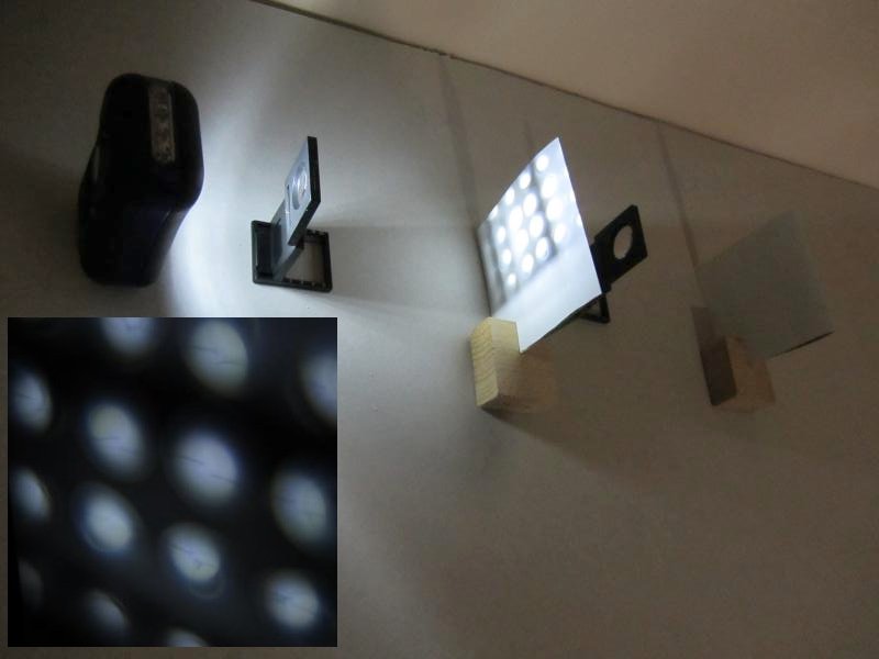
Image: intermediate image (author: Christian Feldhaus)
- The object must have a distance between 1 and 2 focal lengths from the objective to allow a magnified image. If the focal length is written on the lens holder, a ruler may help to construct the beam path.
Demonstrate that by changing the distance between object and objective, the size as well as the position of the focused intermediate image changes (the screen must be repositioned to find the focused image).
- Position the second magnifying glass, the eye piece. Use either a second screen to magnify the intermediate image from the first screen as a real image on the second screen. This beam path would resemble the one for a camera behind an eye piece. Or, without a second screen, have a student using the eye piece as a magnifying lens so that s/he can see a magnified, virtual image of the intermediate image. This beam path would represent the one for the compound microscope with a human observer. You may have to move the whole construction at this point, so that the eye piece is close to the table edge, to allow for human anatomy.
- Now remove the first screen to demonstrate that the screen showing the intermediate image is not required to produce the image on the second screen or in the student’s eye.
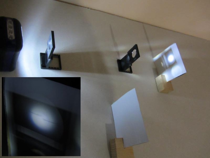
Image: Final image on the ‘second screen’ (author: Christian Feldhaus)
Modifications
- With a 3rd lens you can build a “condenser”; this requires a real sample and comparably strong light source
- The screen showing the final image can be replaced with a lensless digital camera; for that you can get a cheap webcam and take out the lens or use an ocular camera
1. Theory (S/T: 12 (20)):
- Brightfield
- Amplitude objects and phase objects
- Phase contrast
- Differential interference contrast (DIC, Nomarski)
- Polarization microscopy
- Darkfield and Rheinberg
- Oblique illumination and Hoffman modulation contrast
2. Practice (S/T: 2 (4)) (S/I: 2 (4))
- Setting up Köhler alignment
- Influence of the condenser aperture on contrast and resolution (e.g. with Pleurosigma angulatum).
- Demonstration of the various techniques
3. Material
General Resources
Web resources
- Video Understanding the Light Microscope by Peter Evennett on BioDIP you tube channel
The tutorial is presented in one piece, so that it can be viewed in logical order, but its components may be viewed separately by reference to the time-points quoted.- Conjugate Planes in the microscope (0 – 21:00 min)
The optical system of a microscope embodies two series of planes which are conjugate – optically linked, as images one of another. These are the ‘Field’ set of planes consisting of the object and its images, and the ‘Aperture’ set of planes which includes the light source (lamp filament) and it subsequent images. These planes are demonstrated here using a specially assembled microscope and video camera system. - Diffraction and the microscope image (21:00 – 50:51 min)
The most important function of a microscope is resolution – the ability to handle information about fine detail – and this is limited by the phenomenon of diffraction. Two factors are involved – the wavelength of the light, and the Numerical Aperture of the objective lens. The importance of these two factors was demonstrated in 1873 by Ernst Abbe in his ‘Theory of the Microscope’, and illustrated by a series of experiments. These experiments are demonstrated here, again using the specially-adapted microscope. Understanding this section will benefit from having followed section 1. - Dark-field Microscopy (51:41 – 59:40 min)
The second important function of a microscope is to provide contrast in the images of transparent and otherwise invisible objects. Dark-field (or Dark-ground) microscopy offers a simple and inexpensive method of enhancing contrast. It is explained here as a sequel to the Diffraction Experiments, using the same demonstration equipment, and should therefore be viewed following sections 1 & 2. - Phase-contrast Microscopy (59:40 min)
This section demonstrates the principle of a second system of enhancing visibility of transparent objects, Phase Contrast. Again this is demonstrated using the equipment as in earlier sections, and it should therefore be viewed following these.The video was enabled by German Research Foundation (DFG) core facility funding of the Biopolis Dresden Imaging Platform (BioDIP) and has been recorded by Christian Spataro.
- Conjugate Planes in the microscope (0 – 21:00 min)
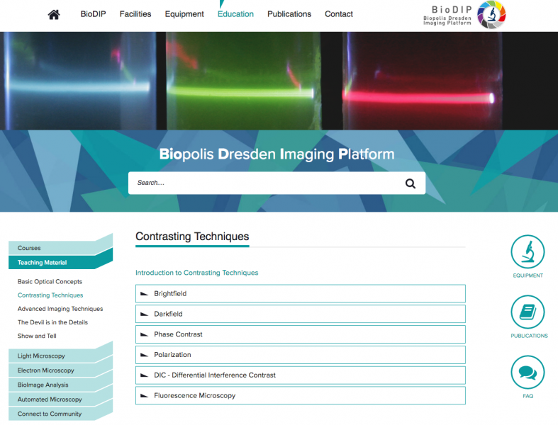
Image: Screenshot BioDIP contrast enhancement (Author: Britta Schroth-Diez)
Polarization and Birefrigence
- Polarization can be nicely demonstrated using two polarization filters:
The video Light extinction by crossed polars on BioDIP you tube channel shows the effect of crossing two polarization filters on light passing through them. When the two polarizers are oriented perpendicular to each other, light gets extinct. - Birefringence can be nicely demonstrated using a calcite crystal and a paper with one black spot:
The video Birefringence on BioDIP you tube channel shows the effect of looking at a black spot through a rotating calcite crystal. There are two spots visible of which one is rotating around the other one. (A nice addition to this demonstration is to rotate a polarization filter on top of the calcite crystal. This will make the spots disappear alternately depending on the polarization direction.)
Modules required to start this module: BMO
1. Theory (S/T: 12 (20)):
- Physico-chemical basics:
- Jablonski diagram
- S0, S1, S2 states
- Fluorochrome characteristics:
- Extinction coefficient, quantum yield, brightness
- Spectral properties
- Stoke’s shift
- Combining several fluorochromes, bleed through and how to avoid it
- The principle of spectral unmixing
- Bleaching and counter measures
- Fluorescence lifetime
- Different kinds of fluorochromes:
- Organic dyes
- Fluorescent proteins
- Quantum dots
- Autofluorescence
- The fluorescence microscope:
- Filters, beam splitters and their positions
- Light sources:
- Spectral properties and handling (including safety issues)
- Lamps: halogen, metal halide, LED, mercury vapor
- Lasers
2. Practice (S/T: 4 (6)) (S/I: 2 (4)):
- Fluorescence microscopy with test samples
- Measurement of bleaching (time series)
- Demonstration of bleed through
- Demonstration of diffraction rings by focusing through point emitters (beads, quantum dots…)
- Measurement of chromatic aberration in 2D (also in 3D if automated z-drive is available)
3. Material
1. Theory (S/T: 12 (20)):
- Pixels and voxels
- Nyquist
- Poisson noise, photons and contrast
- Signal-to-noise
- Dynamic range/ saturation/ bitdepth
- File formats
- Caveats of image manipulation
2. Practice (S/T: 6 (10)) (S/I: 2 (4)):
- Capture an image
- Estimate SNR and background level
- Put in a scalebar
3. Material
Presentation
The Basics of Digital Imaging (BDI).pptxcontains a Powerpoint presentation with slides for a lecture on Basic Microscope Optics.
Liege Guillemins
What you can do with this image:
- look at the repetitive pattern of the roof, draw horizontal intensity profiles on different positions or at the same position at different image scalings: Nyquist theorem
- point at the dark area below the train and the headlights: an area of the image with black or saturated pixels contains no structural information (although we know that there must be structure in both areas)
- play with different contrast, reduce the bitdepth and check the image histogram to demonstrate the loss of information
- save the image in different file formats and then substract from the original to demonstrate how the information change
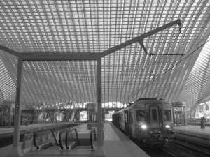
Image: Liege Guillemins
1. Theory (S/T: 12(20)):
- The confocal principle
- Beampath in a confocal laser scanning microscope, scanning, zooming
- Confocal resolution and optical sectioning; pinhole size
- Confocal detection of fluorescence and reflection; laser transmission detection
- Equipment:
- Point detectors: PMTs, GaAsPs and Hybrid detectors
- Acousto-optical devices: AOTF, AOM, AOBS and the like
- Spectral detection: Prisms, Meta detector, spectrometer, interferometer
- Spectral sensitivity of detectors
- Sources of noise
2. Practice (S/T: 2(4)) (S/I: 2(4)):
- Confocal microscopy with test samples: zoom and resolution
- Demonstration of bleed through
- Recording of a PSF, FWHM measurement
- Measurement of chromatic aberration in 3D
- Reflection confocal microscopy and transmission images
3. Material
Presentations
The following links contain Powerpoint presentations with slides for a lecture on confocal microscopy, including two movies: Confocal laser scanning microscopy
- Movie combinded confocal and unconfocal cleared
- Movie confocal cleared only
The following link contains a Powerpoint presentation with slides for a lecture on resolution in fluorescence microscopy: Resolution in Fluorescence Microscopy
Schematic drawings of the confocal principle
These schemes are also included in the Powerpoint presentation Confocal laser scanning microscopy.
1: 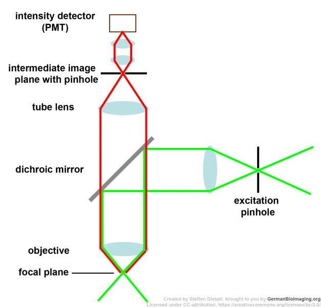 2:
2:  3:
3: 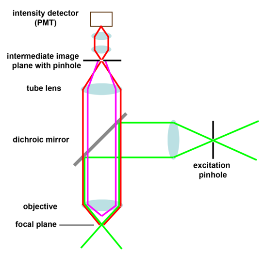
4: 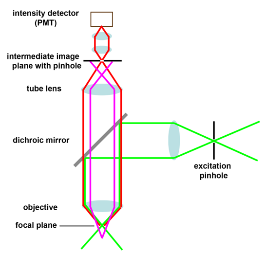 5:
5: 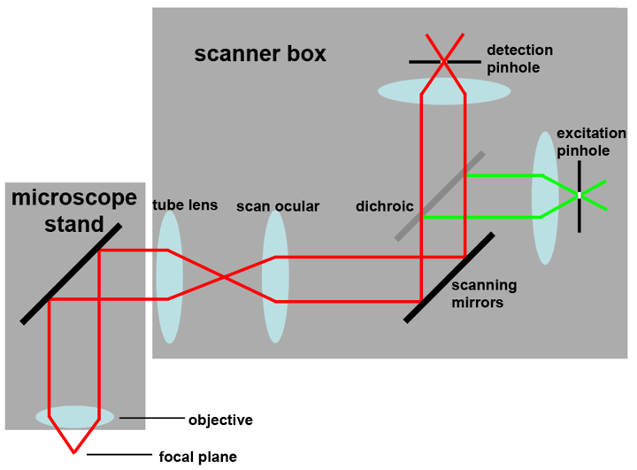
1: Confocal principle 2: Scanning mirror position 3: Fluorescence from above the focal plane
4: Fluorescence from below the focal plane 5: Example for layout in a commercial confocal
1. Theory (S/T: 12 (20)):
- Applications in
- Fluorescence microscopy
- (Patho-)histology
- Remote sensing
- Different acquisition methods for hyperspectral datasets
- Lambda scanning
- Spectral array detector
- Interferometer
- Different methods to analyse spectral datasets (for each also mentioning the required control/ reference samples)
- Spectral unmixing
- Linear unmixing
- Blind unmixing (e.g. PoissonNMF tool in ImageJ)
- Spectral mapping
- Spectral unmixing
2. Practice (S/T: 2 (4)) (S/I: 2 (4))
- Acquisition of a multichannel image of a sample with bleedthrough and unmix it/ analyse it with different spectral tools
- Acquisition of a hyperspectral image (spectral information on each pixel of a sample) with bleedthrough and unmix it/ analyse it with different spectral tools
3. Material
easy-to-build sample for spectral unmixing
- get a small piece of thin paper/ tape and put it on a slide
- draw a line with a yellow highlighter across the paper and a short range across the adjacent glass surface
- draw another such line with a red highlighter, it should cross the yellow line on the paper
- mount such that the paper and the parts of the lines on glass are all covered by a coverglass; as most mounting media will dissolve the dyes try mounting without mounting medium, only fixing the coverslip on the edges.
- you now have a sample with 3 spectral components (yellow highlighter, red highlighter, paper) with overlapping spectra. Using not too narrow bandpass filters you will be able to observe bleedthrough. On the slide, each component can be measured in its “clean” form to take a reference but is also available mixed with the other components.
1. Theory (S/T: 12(20)):
- Grayscale, RGB, false colors, lookup tables (LUTs)
- How to measure: resolution, chromatic aberration, size (micrometer)
- How does human vision work?
- Colour Blindness
- (Colour) sensitivity
- Image enhancement vs. data manipulation: limits, pitfalls, do’s&don’t’s
2. Practice (S/T: 6 (10)) (S/I: 2 (4)):
- Create a RGB image and an image with 4+ channels
- Experiment with visualising the data
- Adjust images for colour blind vision with vischeck plugins
- Brightness and contrast adjustment
- Measure pixel size and image size with an object micrometer
- Make a scalebar
- Measure the FWHM of the PSF in x,y and z.
3. Material
The following file contains a Powerpoint presentation with slides for a lecture on Image processing and presentation: Image processing and presentation (IPP)
The following is a recommendation and may have to be adapted to the circumstances of an imaging site depending on e.g. staff situation or complexity of instrumentation.
Before Going to the Microscope
- Before the training, the general experimental design should be discussed with the user (and his/her supervisor if applicable).
- What’s the biological question and which is the ideal instrument for answering it
- Sample preparation
- How will the data be analysed
- Introduce user to imaging resources at hand (staff, wiki, books, internet resources, etc.)
- Admin stuff
- Booking system
- Facility rules
- Usage costs
- Registration
- Safety issues (biosafety, lasers, waste, working in dark rooms etc.)
1st Training Session
- Background to general light microscopy techniques, eg. contrasting techniques, fluorescence, beampath, pinhole, detector etc. (possible without microscope)
- Introduction to hardware: how to switch on/off.
- Introduction to software: how to properly acquire an image, z-stack, time series, etc.
- Set up an imaging experiment from scratch (with a known sample)
- Data handling (original and exported file formats, metadata, where to store data and backups) and data safety
- Cleaning up of microscope and workplace
2nd Training Session
- 2nd training session with the user involves applying the knowledge from the 1st training on own samples
- After user introduction to a microscope, the user should receive guidance and support from facility staff when imaging their own samples for the first time
Full User Status
- User has to sign facility user rules
- If applicable, user needs to sign laser safety rules
- If applicable (e.g. external user), the users group leader has to sign a declaration for cost assumption (should ideally happen before the introductions already)